

In this article, we understand Intel’s PL1 and PL2 power limits in different layers. But, at a very basic level, PL2 is what the chip may pull in a burst. PL1 is what it may average over time. Tau is the time constant that connects them.
PL1 is the long-term or sustained power limit. For example, if a CPU has a PL1 of 125 watts, Intel wants the CPU to be able to run demanding workloads around this power range continuously.
On the other hand, PL2 is the short-term turbo power limit. PL2 allows the CPU to consume more power temporarily to achieve higher clock speeds.
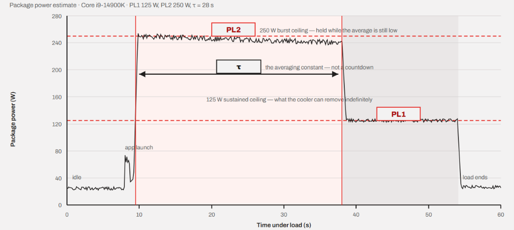
Tau is what decides how long the CPU can stay at PL2. Tau is associated with the turbo power behavior. It basically determines how long the CPU is allowed to operate above its sustained PL1 before the power management system switches back to PL1.
Modern CPUs and Power as a Currency
A modern CPU can have billions of transistors that need to be turned on and off simultaneously to make things happen. And we are talking about billions of times per second. Every switch requires a small amount of charge, and this costs energy. Electric energy, to be specific. These transistors take time to switch. And to switch faster, or in other words, to increase the performance, more voltage will be required. So, when the CPU raises the frequency, a higher voltage will be the first requirement.
At a fixed voltage, power scales roughly linearly with clock frequency. But in practice a higher clock needs a higher voltage, and power scales with the square of voltage. So, the real-world power will climb far faster than the clock does.
For example, if a core needs 1.0 V at 4.0 GHz and 1.3 V at 5.5 GHz, the frequency went up 37%. Power went up by 1.37 × (1.3/1.0)² ≈ 2.3×. So, we basically paid 130% more power for 37% more speed. This relationship is called the V/F curve, and it bends sharply upward at the top. This means the last 300 MHz on a modern chip can cost the power similar to what the initial 3 GHz will consume.
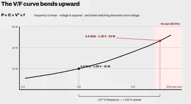
Now, scale that across cores, as we see in the modern CPUs. If one core takes 25 watts and 5.7 GHz, sixteen cores would require 400 watts. Realistically, no desktop cooler can remove 400 watts easily. So, the chip has to choose between these options: very fast few cores or many moderately fast cores. It cannot have both.
So, to be more specific, power is the budget the CPU spends to buy frequency. PL1 and PL2 set the size of that budget.
In electronics, there is also leakage current (static power). This is the current that trickles through transistors even when idle. It grows as the chips become hotter and starts a feedback loop. Hotter chip → more leakage → more power → hotter chip. This is the reason a consistent 100°C is worse than it sounds.
Why two limits rather than just one?
The reason is simple. There are two limits because the CPU and its cooling system react to heat on different timescales. Although the CPU faces all the heat right away as it is pushed with a heavy workload, the cooler doesn’t respond instantly. The cooler’s heatsink is a thick mass of metal, which takes time to absorb heat. Only after it warms up does the difference between heat in and heat out start to push the CPU die temperature up.
Think of it like a bucket with a hole in it.
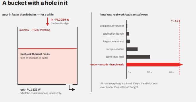
Now, imagine that the hole is the cooler’s steady-state heat dissipation. The bucket’s volume is thermal mass. If you want, you can add water faster to the bucket for a little while until it overflows. The draining will keep going at the same pace.
Almost all the modern consumer workloads are bursty in nature. Whether you launch an application, open a large spreadsheet, compile one file after an edit, or load a game file, there is hardly a situation where the burst load is longer than 30 seconds. Only a handful of things like video encoding, 3D rendering, or large compilations put sustained heavy loads on the processor.
So, it is all about utilizing the temperature headroom that the CPU coolers allow us. However, after some time, the entire heatsink will become hot, and the cooler will start to dissipate the heat closer to its TDP, and this is when your burst speed has to reach an end.
A single power limit will set a bar. If we set it low, every burst will feel sluggish, even though the cooler is sitting idle. Alternatively, if we set it high, the sustained work will cook the machine.
So, the PL2 is there to spend the thermal buffer aggressively and make the machine feel faster. PL1 is the sustained budget whose heat can be removed indefinitely by the cooler. Tau decides how quickly the machine transitions from the first to second.
A little on Tau
As discussed above, Tau tells roughly how long the CPU can sustain power above its long-term PL1 before the power comes down to the base levels. Tau tells the time, but it isn’t necessarily a stopwatch. It is very dynamic and based on various things like workload, ambient temperature, and other limits affecting behavior.
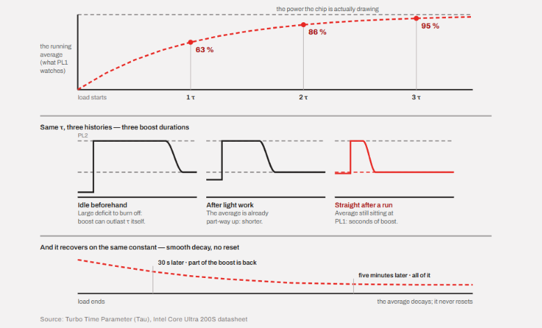
For example, a 10-second workload may finish entirely during a high-power boost period, while a 2-minute sustained load can start at PL2 and then come down to PL1. Additionally, a one-hour render is much more dependent on the sustained power and good cooling.
Obviously, we would like to have a higher Tau window for sustained heavy loads, but the laws of physics make it impossible. We always have to settle for a very high boost for a very short time or good enough sustained speed for long durations. We can’t have both.
To understand Tau better, run Cinebench. Let it finish. Immediately run it again.
The second run will boost for less time than the first, because the average is still elevated from the first run.
The four power limits of Intel CPUs
Yes, there are PL3 and PL4 power limits as well.
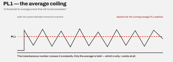
PL1 is the average ceiling, and Intel describes it as the threshold for average power that will not be exceeded. It should be equal to the processor base power and not be set higher than what the cooling solution can handle.
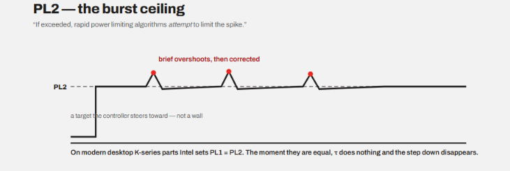
PL2 is the burst ceiling, and Intel says that it is a threshold that, if exceeded, will be attempted to limit using the limiting algorithms. So, the spike will be limited before it becomes dangerous. So, PL2 is the target, not a hard wall. We can always expect brief overshoots.
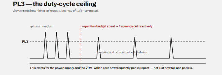
PL3 is the duty-cycle ceiling. PL3 limits how often spikes above it can happen. If the PL3 is exceeded, it controls the further spikes by cutting frequency.
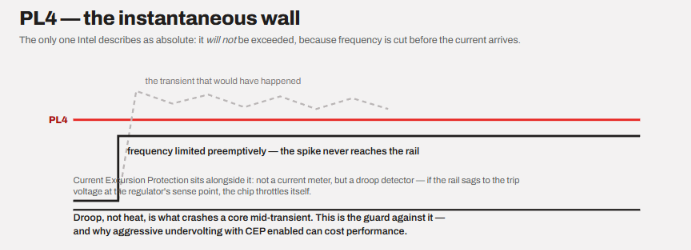
PL4 is the instantaneous wall, and Intel says that it cannot be exceeded. They said that the algorithms limit frequency preemptively to stop spikes before they happen. It is disabled by default on the desktop.
Intel says that implementing Turbo Boost 2.0 only requires the configuration of PL1, PL2, and Tau. PL3 and PL4 are tools for laptops and small form factor devices.
We can summarize all these limits like this: PL1 governs an average. PL2 is a soft target. PL3 governs repetition. PL4 is absolute.
How do the PL1 and PL2 numbers impact the end user?
Intel publishes the power numbers in their processor specification but not directly the PL1 and PL2 figures. However, we can roughly correspond the processor base power as PL1 and maximum turbo power as PL2.
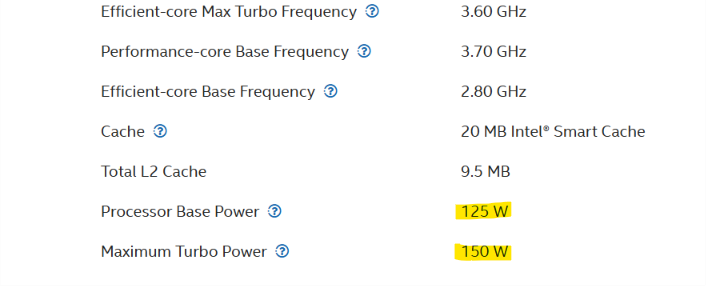
These numbers alone don’t tell you exactly how much power the CPU will use consistently and under load. As a user or buyer, you can hardly do anything meaningful with these numbers. Although PL1, PL2, and Tau can be changed with some tweaks or overclocking, this isn’t generally suggested to everybody.
And increasing these values is generally not worth it because the higher PL2 mostly buys more heat, and if the cooler is not capable, it will result in throttling. Higher PL1 can be good to improve the overall performance, but it requires good cooling as well. All in all, I wouldn’t advise playing with these things. Also, as a buyer, there are other important things to look for rather than just these PL1 and PL2 numbers.
In fact, Puget System ran a controlled test on a Core i9-14900K, comparing PL1 = 125 W against PL1 = 253 W. The performance gains were something like this:
| Application | Gain from 125 W to 253 W |
|---|---|
| Photoshop, Lightroom | Under 3%, within margin of error |
| Premiere Pro | No measurable difference |
| After Effects | About 4% |
| DaVinci Resolve | About 7% |
| Unreal Engine shader compile | About 8.5% |
| V-Ray | About 11% |
| Blender | About 14% |
| Cinebench 2024 | About 18% |
My take from this is that if you render or compile for a living, the higher limits are worth it for you. But you will have to buy a cooler that properly absorbs the heat that the processor generates. Otherwise, you will just be paying the heat cost without any significant performance gains. For tasks like gaming, browsing, and most other creative works, playing around with the PL1 isn’t worth it.
The change in modern K-series chips
What we discussed above was a classic two-tier system that bursts at PL2 and settles at PL1. But the modern desktop K-series chips with and after the 12th generation (Alder Lake), the PL1 is set equal to the PL2. Both are set at maximum turbo power.
Now, when these two values match, the Tau loses its role. There is no step-down and boost decay. So, a chip can run at 253 watts or 250 watts on a Core Ultra 9 285K as long as the workload lasts.
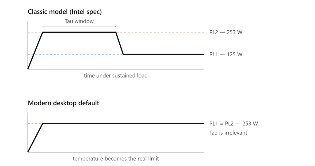
However, the mechanism didn’t change, and the Turbo Boost 2.0 works exactly the same. But PL1 stopped meaning “what the cooler can handle continuously” to “the same as PL2.”
Power limit is just one of five ceilings
The first ceiling is the power limits (PL1, PL2, PL3, and PL4), as we discussed above. But there are temperature, current, current excursion protection, and the V/F curve deciding when a CPU can hit its peak. So, in the latest processor with the same PL1 and PL2, the CPU relies on these external factors.
So, every ceiling you remove exposes the next one. Nothing is ever actually unlimited.
How to check and change your own limits?
I have created a table to give you an idea of how to identify PL1, PL2, Tau, and current in your BIOS, Intel XTU, or HWiNFO, if you want.
| Concept | BIOS (typical) | Intel XTU | HWiNFO | Linux |
|---|---|---|---|---|
| PL1 | Long Duration Power Limit | Turbo Boost Power Max | Power Limit 1 | constraint_0_power_limit_uw |
| PL2 | Short Duration Power Limit | Turbo Boost Short Power Max | Power Limit 2 | constraint_1_power_limit_uw |
| Tau | Package Power Time Window | Turbo Boost Power Time Window | — | constraint_0_time_window_us |
| Current | CPU Current Limit / IccMax | Core Current Limit | — | — |
If you want to change these, BIOS is the right place mainly because it writes the registers at boot. Intel XTU applies its settings at every Windows login and does not touch BIOS.
How does AMD do it differently?
AMD uses three limits. PPT (package power tracking, in watts), TDC (thermal design current, sustained amps), and EDC (electrical design current, peak amps). People usually map PPT onto PL1.
There is a structural difference in both. AMD defines a single sustained power ceiling and holds it. You will find no Tau equivalent in AMD, nor the burst-then-settle pair. They rely on Precision Boost 2, which continuously adjusts frequency based on live power, current, and temperature headroom. Basically, the budget does not change over time.
In other words, AMD defines a maximum that the CPU can never exceed, while Intel keeps the specification looser.
Conclusion
For a normal end-user, there is no need to pay extra attention to these numbers. I would also not recommend you playing around with the BIOS and trying to change these numbers if you don’t know what you are doing. If you want to make any changes, I would recommend researching well on the values and going through some guides. Otherwise, processor companies know where to set bars for temperature and power consumption.